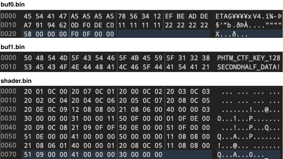
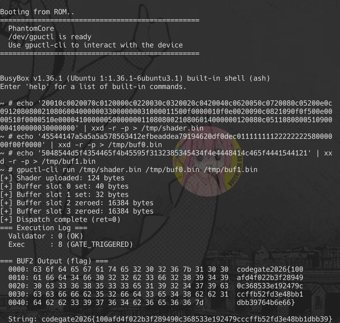
Challenge: PhantomCore - Codegate CTF 2026 Quals
TL;DR
┌──────────────┐ ioctl ┌──────────────┐ MMIO ┌──────────────┐ │ gpuctl-cli │ ───────────────▶ │ gpuctl.ko │ ──────────────▶ │ phantom-gpu │ │ (userspace) │ /dev/gpuctl │ (kernel) │ BAR0 │ (QEMU) │ └──────────────┘ └──────────────┘ └──────┬───────┘ │ ┌─────────────────────────────────────────────────────┴─────┐ │ │ ▼ ▼ ┌─────────────────┐ ┌────────────────────┐ │ INIT PATH │ │ RUNTIME PATH │ │ │ │ │ │ blob @ 0xb0a2d8│ │ UPLOAD_SHADER │ │ ↓ │ │ ↓ │ │ xorshift32 │ │ DISPATCH │ │(seed=0xfe170e07)│ │ ↓ │ │ ↓ │ │ Validate + Exec │ │ CRC + LZ4 │ │ ↓ │ │ ↓ │ │ opcode → hash │ │ 0x308 bytes ───┼──────────────────────────────────────▶ → handler table │ │ (state blob) │ │ ↓ │ └─────────────────┘ │ regs/stack/DMA │ └───────────────────PhantomCore is a rev challenge built around a VM inside a custom QEMU PCI device (phantom-gpu). You need to craft shader bytecode that clears all 6 gate conditions, then recover the hidden witness (register values + 32 bytes of buf1) buried in the firmware blob to get the flag.
The solve breaks down into two stages:
- Pass the Gates: find a shader + buffer combo that satisfies all 6-bit conditions from the checker
- Recover the Flag: even after passing the gates, the success path reads additional inputs (reg0/reg3/reg4/reg5, raw 32 bytes of buf1) that must be exact for the correct flag to come out
This writeup focuses more on the overall structure and flow than on the nitty-gritty reversing.
1. Overall Architecture
1-1. Background: GPU and CPU
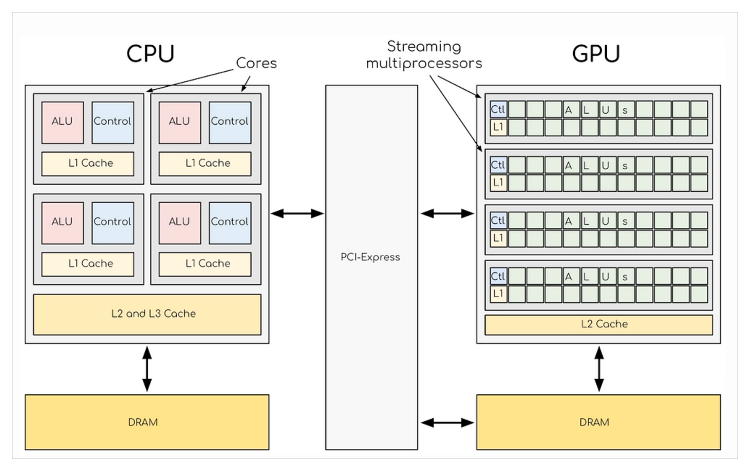
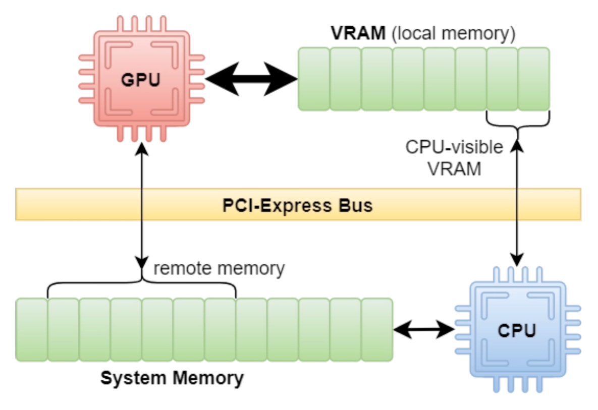
The GPU is a separate physical device connected to the CPU over PCIe. CPU has its own DRAM, GPU has its own VRAM, and data moves between them via DMA over PCIe.
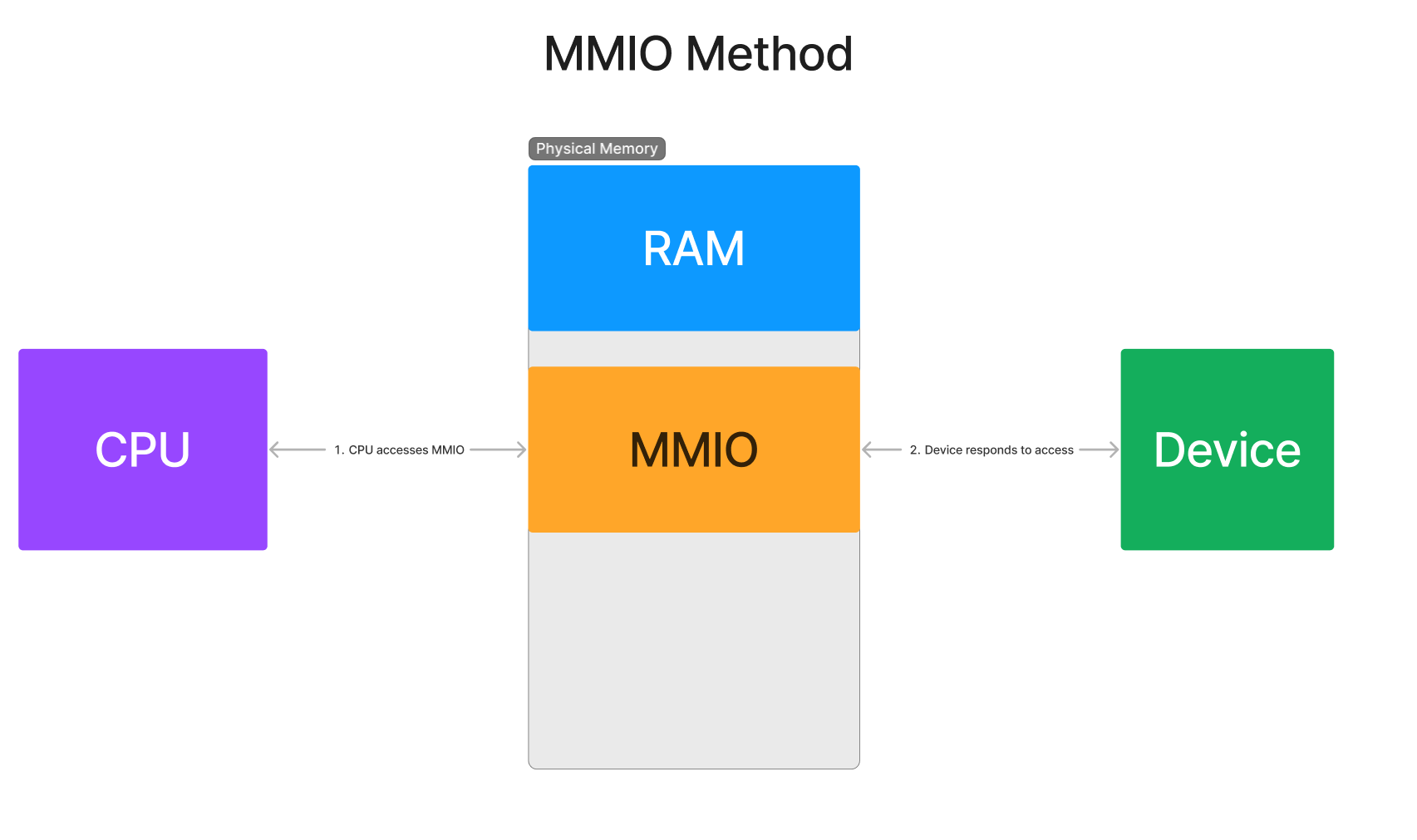
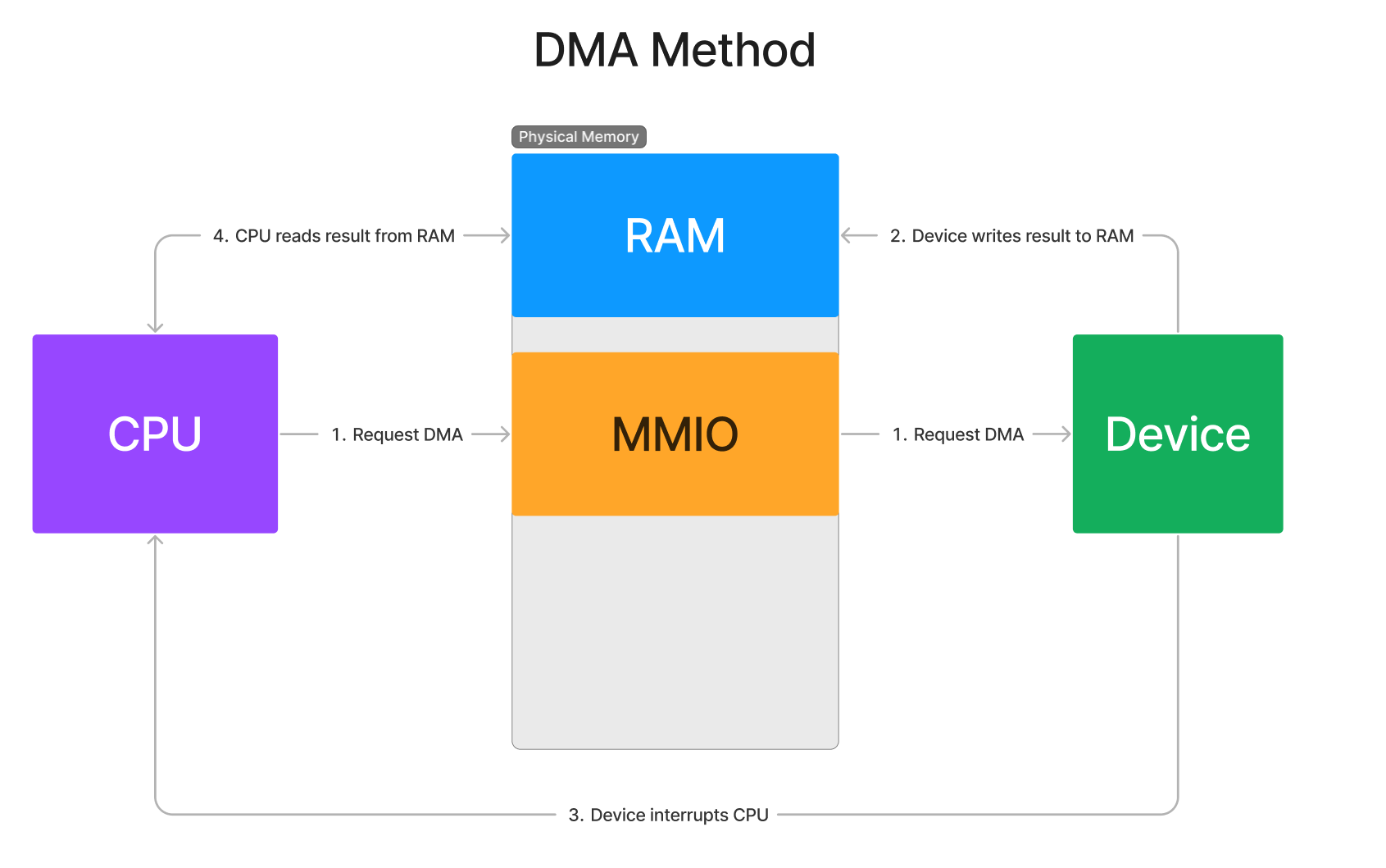
The driver talks to the GPU in two ways:
- MMIO (control plane): CPU reads/writes GPU registers mapped at BAR0 to send commands and config. No bulk data moves here—just signals.
- DMA (data plane): GPU becomes the PCIe Bus Master and transfers data directly between Host Memory ↔ Device Memory, no CPU involvement.
The directions are opposite, which is why they’re separated: MMIO is CPU → device, DMA is device → RAM.
1-2. Implementation in QEMU
Reference: PCI vs PCIe - QEMU Wiki
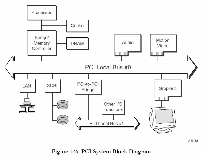
Legacy PCI was a shared bus architecture consisting of CPU, Bridge/Memory Controller, Bus, and devices connected to it. The Host Bridge (northbridge) connected CPU/DMA to the bus, and bus arbitration determined bus usage rights.
Reference: QEMU PCI Device Implementation - owalle
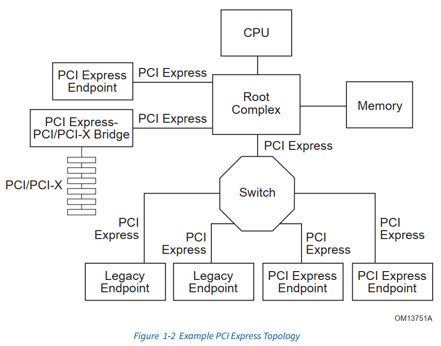
This challenge uses -machine q35 to emulate a PCIe-based platform. In PCIe, the Root Complex integrates the roles of the traditional Host Bridge and memory controller, eliminating the need for a separate northbridge chip. Instead of a shared bus, each device connects to the Root Complex via point-to-point links.
Device list confirmed via /sys/bus/pci/devices:
[0000:00] pcie.0 (Root Complex = q35 MCH) ├── 00:00.0 Intel 82G33 Host Bridge vendor=8086:29c0 class=0x060000 ├── 00:01.0 phantom-gpu (Accelerator) vendor=1de5:7001 class=0x0b4000 ← DRIVER=gpuctl ├── 00:1f.0 ICH9 LPC Controller vendor=8086:2918 class=0x060100 ├── 00:1f.2 ICH9 SATA Controller vendor=8086:2922 class=0x010601 └── 00:1f.3 ICH9 SMBus Controller vendor=8086:2930 class=0x0c0500Since there are no separate bridges or switches in the bus structure, the challenge environment is a single PCIe topology with direct connections from Root Complex to Endpoint, as shown in the [PCI Express Topology] diagram. The phantom-gpu can be seen as the device corresponding to the Graphics position in the [PCI System Block Diagram].
Meanwhile, phantom-gpu has an MMIO region mapped through BAR0:
BAR0: 0xfebfe000 ~ 0xfebfefff (4KB MMIO region)This represents the memory space for register access to the device.
Reference: Getting Started with QEMU - velog
QEMU Process Memory:
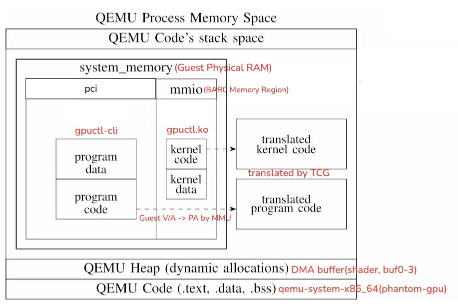
A real GPU is an external physical device on PCIe, but phantom-gpu is just a virtual device implemented in C inside the QEMU process. What would be physically separate VRAM is really just a chunk of Guest RAM here, accessed through dma_memory_read/write().
QEMU Abstraction Layer:
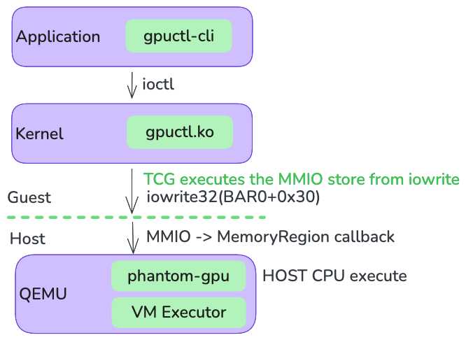
QEMU Internal Modules:
- TCG: Emulation engine that JIT-translates Guest x86_64 instructions for execution on the Host CPU
- MMU: Guest virtual address → physical address translation. Dispatches to MemoryRegion callback on BAR0 MMIO access
- QDEV: PCI device emulation framework. phantom-gpu is registered here
The challenge runs in pure TCG mode (no enable-kvm). Whenever an MMIO address (BAR0 region) gets touched during execution, the MemoryRegion callback mapped to that address fires and we land in the phantom-gpu handler.
For reference, the official QEMU PCI device implementation example can be found at hw/misc/edu.c.
phantom-gpu follows similar patterns to the official example—BAR0 MemoryRegion registration, DMA access, interrupt handling—with a shader VM added on top.
1-3. phantom-gpu vs. Real GPU
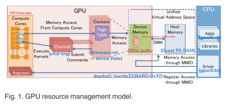
Real GPU Compute Cores are parallel hardware, but the phantom-gpu VM executor is just a sequential software interpreter that reads and runs instructions one at a time. No separate MMU, no memory isolation. It decodes the firmware blob, sets up S-box, constants, key material, etc. in the device’s internal struct, and that becomes all the global state the VM needs.
2. Challenge File Overview
├── bios/│ ├── bios-256k.bin <- Required│ ├── efi-e1000e.rom <- Not needed (-nic none)│ ├── efi-virtio.rom <- Not needed│ ├── kvmvapic.bin <- Not needed (No KVM, only TCG)│ ├── linuxboot_dma.bin <- Not needed│ └── vgabios-stdvga.bin <- Not needed (-vga none)├── bzImage # Guest Linux kernel├── initramfs.cpio.gz # Guest root filesystem├── qemu-system-x86_64 # Custom QEMU binary <- Analysis target└── run.shThere are 6 files in the bios/ directory, but only bios-256k.bin is actually needed.
-machine q35 requires BIOS, which handles the POST process before booting the Guest Linux kernel. The other 5 files are unnecessary if you just add -nic none, -vga none options to the original run.sh.
Extracting initramfs:
mkdir initramfs_root && cd initramfs_rootgzip -dc ../initramfs.cpio.gz | cpio -idmv.├── bin│ ├── busybox│ ├── cat -> busybox│ ├── chmod -> busybox ├── hexdump -> busybox│ ├── cp -> busybox ├── insmod -> busybox│ ├── dd -> busybox ├── ls -> busybox│ ├── dmesg -> busybox ├── mount -> busybox│ ├── echo -> busybox ├── od -> busybox│ ├── grep -> busybox └── xxd -> busybox├── init├── lib│ └── modules│ └── gpuctl.ko <- Kernel module└── usr └── local └── bin └── gpuctl-cli <- Userland CLIThe init script insmods gpuctl.ko and creates the /dev/gpuctl character device.
#!/bin/shmount -t proc none /procmount -t sysfs none /sysmount -t devtmpfs none /devmkdir -p /dev/ptsmount -t devpts none /dev/ptsmount -t tmpfs none /tmp
export PATH=/bin:/sbin:/usr/local/bin
# Load phantom-gpu driverinsmod /lib/modules/gpuctl.kosleep 0.5
echo "================================================"echo " PhantomCore"echo " /dev/gpuctl is ready"echo " Use gpuctl-cli to interact with the device"echo "================================================"
# Drop to shellexport PATH=/bin:/sbin:/usr/local/binexport HOME=/tmpcd /tmpsetsid cttyhack sh
poweroff -fRunning run.sh:
================================================ PhantomCore /dev/gpuctl is ready Use gpuctl-cli to interact with the device================================================BusyBox v1.36.1 (Ubuntu 1:1.36.1-6ubuntu3.1) built-in shell (ash)Enter 'help' for a list of built-in commands.
~ # gpuctl-cliUsage: gpuctl-cli <command> [args...] upload <shader.bin> Upload shader bytecode setbuf <slot> <file.bin> Set buffer slot (0-3) dispatch [max_steps] Dispatch shader execution run <shader.bin> [buf0] [buf1] One-stop upload+set+dispatch log Read last execution log3. Reversing gpuctl-cli (Userland)
Let’s start with gpuctl-cli.
Found the main function (sub_401BA0) in IDA by xref-ing the "Usage: %s <command>" string.
upload / setbuf / dispatch / log are each just thin ioctl wrappers, and run does all of them in one shot.
int cli_main(int argc, char **argv) { if (argc <= 1) { print_usage(); return 1; } int fd = open("/dev/gpuctl", O_RDWR); if (fd < 0) { perror("open(/dev/gpuctl)"); return 1; } const char *cmd = argv[1];
if (!strcmp(cmd, "upload")) { if (argc != 3) error("upload: need <shader.bin>"); else rc = upload_shader(fd, argv[2]); } else if (!strcmp(cmd, "setbuf")) { if (argc <= 3) error("setbuf: need <slot> <file>"); else { slot = parse_uint(argv[2]); if (slot > 3) error("slot must be 0-3"); else rc = set_buffer_from_file(fd, slot, argv[3]); } } else if (!strcmp(cmd, "dispatch")) { max_steps = (argc == 2) ? 0x100000 : parse_uint(argv[2]); out = calloc(1, 0x4000); rc = dispatch(fd, max_steps, out); free(out); } else if (!strcmp(cmd, "run")) { if (argc == 2) error("run: need at least <shader.bin>"); else { upload_shader(fd, argv[2]); if (argc >= 4) set_or_clear(fd, 0, argv[3]); // buf0 else clear_buf(fd, 0); if (argc >= 5) set_or_clear(fd, 1, argv[4]); // buf1 else clear_buf(fd, 1); clear_buf(fd, 2); // buf2: 16KB zeroed ← flag output area clear_buf(fd, 3); // buf3: 16KB zeroed ← stack area out = calloc(1, 0x4000); rc = dispatch(fd, 0x100000, out); if (!rc && read_log(fd, &logrec, 8) > 0) { print_log(logrec); if (logrec.status == 8) // GATE_TRIGGERED dump_buf2_as_flag(out); } free(out); } } else if (!strcmp(cmd, "log")) { if (read_log(fd, &logrec, 8) < 0) perror("read(log)"); else print_log(logrec); } else { print_unknown_command(cmd); print_usage(); rc = 1; } close(fd); return rc;}As users, we just use run to upload shader, buf0, and buf1. run automatically allocates buf2 (flag output) and buf3 (stack) as 16KB zeroed buffers.
The logrec.status == 8 check stands out—as we’ll see later, that’s the GATE_TRIGGERED state. buf2 only gets dumped as the flag when this fires.
The ioctl codes: upload=0x40105001, setbuf=0x40105002, dispatch=0xC0185003.
4. Reversing gpuctl.ko (Kernel Module)
References
To make sense of gpuctl.ko, it helps to first understand the standard PCIe DMA flow.
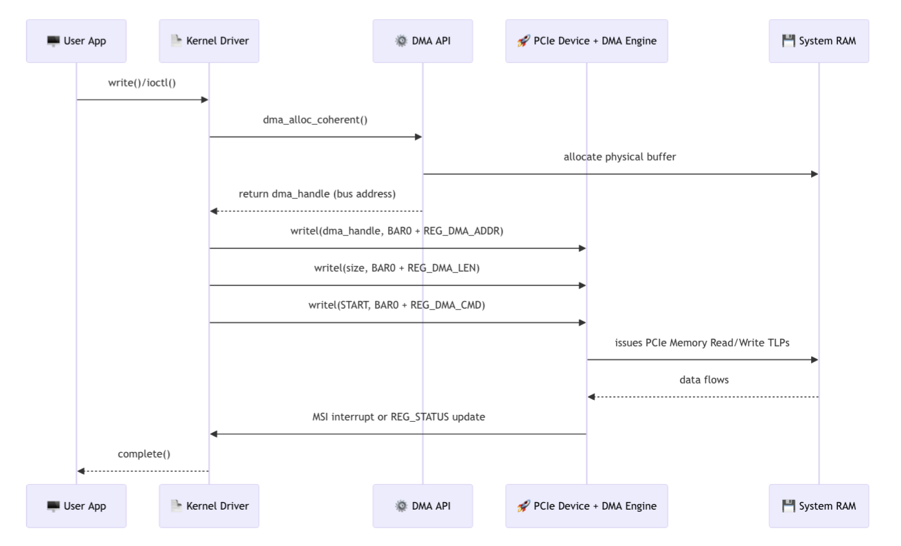
Unlike the diagram, phantom-gpu has no physical PCIe TLP. When iowrite32(bar0+0x30) triggers a guest MMIO trap, the QEMU MemoryRegion callback just reads guest RAM directly via dma_memory_read(cmd_ring_dma). Same interface from the driver’s perspective, but no PCIe fabric underneath.
gpuctl.ko is a pure forwarding layer. It follows the typical PCIe driver pattern—DMA buffer alloc → tell the device the addresses → ring the doorbell → wait for interrupt—split into three parts: initialization (probe), command delivery (ioctl), and completion reception (IRQ).
4-1. From init_module to probe
unk_11A0 is the pci_driver struct. Looking at that address in IDA:
__int64 init_module() { return pci_register_driver(&pci_driver_struct, &_this_module, "gpuctl");}.data:11B0 dq offset "gpuctl" → .name.data:11B8 dq offset id_table → .id_table (vendor=1DE5, device=7001).data:11C0 dq offset sub_650 → .probe.data:11C8 dq offset sub_30 → .removeWhen pci_register_driver registers this struct with the kernel, the kernel scans the PCI bus and automatically calls .probe = sub_650 when it finds a device with vendor=1DE5, device=7001 (phantom-gpu).
4-2. probe(sub_650) — PCI Initialization and DMA Allocation
-
PCI Activation and BAR0 Mapping
pci_enable_device(pdev);pci_request_regions(pdev, "gpuctl");gd->bar0 = pci_iomap(pdev, 0, 4096);// Signature verificationsig = ioread32(gd->bar0 + 0x00);// sig == 0x5048544D ("PHTM") requiredpci_iomapmaps the BAR0 physical address to kernel virtual address. After this, reading/writing to this address viaioread32/iowrite32triggers MMIO access, which triggers QEMU’s MemoryRegion callback. -
DMA Buffer Allocation and Address Delivery
For a PCIe device to directly access host RAM, the OS needs to allocate contiguous physical memory first, then tell the device that address. Writing the address to BAR0 doesn’t kick off any transfer—it just tells the device “read from here later.”
// Request DMA buffer allocation from OSgd->cmd_ring = dma_alloc_attrs(&pdev->dev, 0x1000, &gd->cmd_ring_dma, ...);gd->log_ring = dma_alloc_attrs(&pdev->dev, 0x1000, &gd->log_ring_dma, ...);gd->shader = dma_alloc_attrs(&pdev->dev, 0x2000, &gd->shader_dma, ...);for (i = 0; i < 4; i++)gd->slot[i] = dma_alloc_attrs(&pdev->dev, 0x4000, &gd->slot_dma[i], ...);The third argument to
dma_alloc_attrs(&gd->cmd_ring_dma) is the pointer that receives the physical address. The device directly accesses guest RAM using this physical address.Next, these addresses are written to BAR0 registers to inform phantom-gpu:
// Write DMA physical addresses → BAR0iowrite32(lower_32_bits(gd->cmd_ring_dma), gd->bar0 + 0x20); // cmd_ring loiowrite32(upper_32_bits(gd->cmd_ring_dma), gd->bar0 + 0x24); // cmd_ring hiiowrite32(lower_32_bits(gd->log_ring_dma), gd->bar0 + 0x40);iowrite32(upper_32_bits(gd->log_ring_dma), gd->bar0 + 0x44);// slots 0~3 similarly written to 0x50~0x6Ciowrite32(0, gd->bar0 + 0x30); // doorbell initializationThis is the PCIe DMA Source Address programming stage. phantom-gpu stores these addresses internally and directly reads from those guest memory regions when commands arrive.
-
IRQ Registration and Firmware Init
// Register MSI interrupt handlerrequest_threaded_irq(irq, sub_5E0, NULL, 0x80, "gpuctl", gd);// Firmware init triggeriowrite32(1, gd->bar0 + 0x100);_mm_mfence();// Poll until QEMU completes firmware blob decodingfor (i = 0; i < 100; i++) {if (ioread32(gd->bar0 + 0x104) == 1) break;udelay(4295);}pci_set_master(pdev); // device can be DMA mastercdev_add(&gd->cdev, ...); // create /dev/gpuctlWriting 1 to
bar0+0x100is the firmware init doorbell. QEMU receives this write, decodes the internal firmware blob, sets up gate constants, then changesbar0+0x104to 1 to signal completion.
4-3. ioctl handler (sub_370) - Command Delivery
When gpuctl-cli sends an ioctl to /dev/gpuctl, this function receives it. sub_370 is the ioctl handler because it’s in the .unlocked_ioctl field of the file ops registered via cdev_init(gd->cdev, &gpuctl_fops) in probe.
This function handles three commands:
mutex_lock(&gd->lock);switch (cmd) {
case 0x40105001: // UPLOAD_SHADER copy_from_user(gd->shader, user_ptr, size); // user → DMA buffer push_cmd(gd, CMD_UPLOAD, size, shader_dma); // write to cmd ring + doorbell wait_event(gd->wq, gd->irq_done); // wait for IRQ break;
case 0x40105002: // SET_BUF copy_from_user(gd->slot[slot], user_ptr, size); push_cmd(gd, CMD_SETBUF, slot|(size<<32), slot_dma[slot]); wait_event(gd->wq, gd->irq_done); break;
case 0xC0185003: // DISPATCH push_cmd(gd, CMD_DISPATCH, max_steps, 0); wait_event(gd->wq, gd->irq_done); copy_to_user(user_out, gd->slot[2], min(out_size, 0x4000)); // return result break;}mutex_unlock(&gd->lock);The role of push_cmd(sub_160) is important here:
// 1. Write 64-byte command to next slot in cmd ring (writes to DMA buffer)memcpy(&cmd_ring[tail], &cmd, 64);
// 2. doorbell write → triggers QEMU MMIO write handleriowrite32(next_idx, gd->bar0 + 0x30);cmd_ring operates as a streaming DMA ring buffer pattern. The driver advances the tail (Producer index) while filling commands, and phantom-gpu consumes from the head (Consumer index).
Fill the DMA buffer first, then wake the device with a doorbell—that’s standard PCIe DMA ordering, and iowrite32(next_idx, bar0+0x30) is that signal. After the doorbell write, phantom-gpu reads cmd_ring via DMA and processes the command.
4-5. IRQ handler (sub_5E0) - Completion Signal
irqreturn_t irq_handler(int irq, void *gd) { u32 status = ioread32(gd->bar0 + 0x14); // check completion status if (status) { gd->log_record = *(u64 *)gd->log_ring; // read log gd->has_log = 1; iowrite32(status, gd->bar0 + 0x18); // IRQ ACK wake_up(&gd->wq); // wake ioctl handler } return IRQ_HANDLED;}After DISPATCH completes, phantom-gpu fires an MSI and this ISR wakes up. It unblocks the ioctl handler that’s been sitting on wait_event, and the result (slot2 = flag output area) gets sent back to userspace via copy_to_user.
4-6. Complete Flow
gpuctl-cli │ ioctl(fd, DISPATCH, ...) ▼sub_370 (ioctl handler) ├─ copy_from_user → DMA buffer (slot[0], slot[1]) ├─ push_cmd │ ├─ write command to cmd_ring[tail] ← streaming ring buffer │ └─ iowrite32(next_idx, bar0+0x30) ← doorbell │ │ │ Real HW: └─ PCIe TLP → device DMA engine → read host RAM │ QEMU: └─ MMIO trap → MemoryRegion callback │ └─ dma_memory_read(cmd_ring_dma) ← direct guest RAM │ │ │ shader validation + VM execution │ MSI interrupt generated │ │ └─ wait_event ◀─────┘ │ sub_5E0 (IRQ handler) ioread32(bar0+0x14) completion status iowrite32(bar0+0x18) ACK wake_up(&gd->wq) │ ioctl handler resumes ◀┘ copy_to_user(slot[2]) → return flag outputAs mentioned, gpuctl.ko is just a forwarding layer—copy to DMA buffer, ring the doorbell, done. The real analysis target is the qemu-system-x86_64 binary.
5. Reversing QEMU phantom-gpu
For QEMU, I started by tracking the "phantom-gpu" string xref in IDA to locate the key functions:
| Function | Description |
|---|---|
sub_4277B0 | PCI class init; "Phantom GPU (CTF Challenge Device)" |
sub_427D10 | device realize; MMIO region registration, BAR activation |
sub_427C10 | MMIO read handler; returns signature/version |
sub_428AB0 | MMIO write handler |
sub_428AB0 is a massive ~6000-line function that packs in all the core logic: firmware init, DMA command processing, shader validation, VM execution, and the post-gate success path.
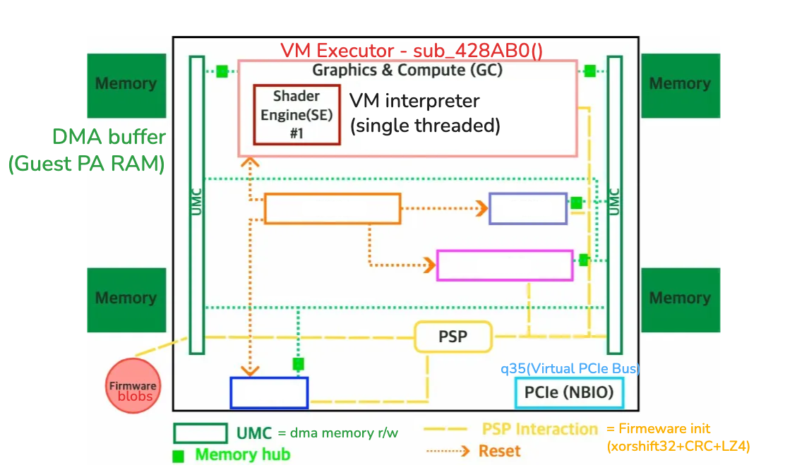
5-1. Firmware Blob Extraction and Decoding
In sub_428AB0, the offset == 0x100 branch is the firmware init path, referencing the embedded blob at 0xB0A2D8.
The decoding chain is straightforward:
; ① xorshift32 — 0x428FE8mov edx, 0FE170E07h ; seedloc_428FE8: mov eax, edx shl eax, 0Dh ; state ^= state << 13 xor eax, edx mov edx, eax shr edx, 11h ; state ^= state >> 17 xor eax, edx mov edx, eax shl edx, 5 ; state ^= state << 5 xor edx, eax xor [rcx], dl ; blob[i] ^= low_byte(state) add rcx, 1 cmp rcx, rbp ; 0x2E1 bytes jnz loc_428FE8
; ② CRC32 — 0x42901Cmov eax, 0FFFFFFFFh ; CRC initloc_429028: movzx edx, byte ptr [rsi] xor edx, eax shr eax, 8 movzx edx, dl xor eax, [rcx+rdx*4] ; table @ 0x19EEF00 cmp rsi, rbp jnz loc_429028cmp eax, 0AEF1393Ah ; expected CRC
; ③ LZ4 raw block — 0x429080movzx ebx, byte ptr [rdx] ; token byte shr al, 4 ; literal_length = token >> 4 cmp al, 0Fh ; if 0xF → extended length loop jz loc_429522Here’s the extraction script.
extract.py
#!/usr/bin/env python3import struct, zlib, sys, lz4.blockfrom pathlib import Path
qemu = Path("qemu-system-x86_64").read_bytes()enc = bytearray(qemu[0xB0A2D8 : 0xB0A2D8 + 0x2E1])
# xorshift32 decrypt (seed=0xFE170E07)state = 0xFE170E07for i in range(len(enc)): state ^= (state << 13) & 0xFFFFFFFF state ^= state >> 17 state ^= (state << 5) & 0xFFFFFFFF state &= 0xFFFFFFFF enc[i] ^= (state & 0xFF)
# CRC32 verify — raw accumulator (no final XOR) == 0xAEF1393Acrc_raw = zlib.crc32(bytes(enc)) ^ 0xFFFFFFFF & 0xFFFFFFFFassert crc_raw == 0xAEF1393A, f"CRC mismatch: {crc_raw:#x} vs 0xAEF1393A"
# LZ4 raw block decompress → 0x308 bytesfirmware = lz4.block.decompress(bytes(enc), uncompressed_size=0x308)Path("firmware_decompressed.bin").write_bytes(firmware)print(f"OK: {len(firmware)} bytes → firmware_decompressed.bin")5-2. Firmware → Device State Copy
The 0x308-byte blob after LZ4 decompression is copied to various offsets of the device state struct. Reconstructing the structure from mov/rep movsq assembly traced in IDA:
typedef struct PhantomGPUState { uint8_t _pci_header[0xC00];
uint8_t key_seed[8]; uint8_t blob_copy[0x308];
uint64_t blob_tail_qword;
uint8_t trace_pattern[8]; uint32_t gate_reg7; uint32_t gate_buf2_dw0; uint32_t gate_crc_buf1; uint32_t gate_xor_r0r3;
uint32_t post_f28; uint32_t post_f2c;
uint64_t dispatch_table[256];
uint8_t _dma_addrs[];
uint32_t reg[16]; uint32_t pc; uint32_t sp; uint32_t cmp_flag;
uint8_t active_shader[0x2000];
uint8_t trace_ring[16]; uint32_t trace_count;
uint32_t gate_armed; uint32_t vm_status; uint32_t fault_code;
} PhantomGPUState;5-3. Phase 1 Transform — Grammar A / Grammar B
I’ll call the firmware blob → gate constant derivation process “Phase 1 Transform.” In the IDA range 0x429240~0x429472, two distinct patterns repeat.
Grammar A (stream XOR) — trace pattern generation
0x429240~0x429261 loop:
loc_429240: lea edx, [ecx+eax] ; edx = (seed + i) — seed is low byte of blob[0x08] movzx edx, dl ; dl = (seed + i) & 0xFF movzx edx, byte ptr [rdi+rdx+0D0Ch] ; dev[0xD0C + dl] = sbox[dl] xor dl, [rax+0C07h] ; ^ blob[i-1] (dev[0xC08+i-1]) mov [rax+0F0Fh], dl ; → dev[0xF10+i-1] (trace pattern) add rax, 1 cmp rax, rsi ; 8 iterations jnz loc_429240Pseudo-code:
// Grammar A: sbox byte XORfor (i = 0; i < 8; i++)
dev[0xF10 + i] = sbox[(seed + i) & 0xFF] ^ blob[i];seed is the low byte of blob[0x08:0x0C] (= dev[0xC10]), sbox is dev[0xD0C] = blob[0xFC:0x1FC]. The result is 50 11 21 40 20 11 51 41 — the expected trace value for gate bit 0.
Grammar B (pack_perm XOR) — 32-bit constant generation
0x42926B~0x4292C1 is the first Grammar B block. Repeating pattern:
mov edx, [rbx+0C18h] ; edx = selector (4-byte value in blob)lea eax, [rdx+1] ; idx+1lea ecx, [rdx+2] ; idx+2movzx eax, byte ptr [rbx+rax+0D0Ch] ; sbox[(selector+1) & 0xFF]movzx ecx, byte ptr [rbx+rcx+0D0Ch] ; sbox[(selector+2) & 0xFF]shl eax, 8 ; byte1 << 8shl ecx, 10h ; byte2 << 16or eax, ecxmovzx ecx, dl ; sbox[(selector+0) & 0xFF]movzx ecx, byte ptr [rbx+rcx+0D0Ch]add edx, 3movzx edx, byte ptr [rbx+rdx+0D0Ch] ; sbox[(selector+3) & 0xFF]or eax, ecx ; | byte0shl edx, 18h ; byte3 << 24or eax, edx ; = pack_perm resultxor eax, [rbx+0C14h] ; ^ XOR source from blobmov [rbx+0F18h], eax ; → dev[0xF18] (gate_reg7)Pseudo-code:
// Grammar B: 4-byte S-box lookup → u32 → XORuint32_t pack_perm(uint8_t *sbox, uint32_t idx) { return sbox[(idx+0) & 0xFF] | (sbox[(idx+1) & 0xFF] << 8) | (sbox[(idx+2) & 0xFF] << 16) | (sbox[(idx+3) & 0xFF] << 24);}
dev[0xF18] = pack_perm(sbox, blob_dword(selector_offset)) ^ blob_dword(xor_offset);This pattern repeats 6 times to generate 6 gate constants:
// (selector offset → XOR source → storage location) mapping traced from IDA:dev[0xF18] = pack_perm(sbox, blob[0x10]) ^ blob[0x0C] // gate_reg7 = 0xA5A5A5A5dev[0xF1C] = pack_perm(sbox, blob[0x18]) ^ blob[0x14] // gate_buf2 = 0xC0DEF00Ddev[0xF20] = pack_perm(sbox, blob[0x20]) ^ blob[0x1C] // gate_crc = 0x2A8DED84dev[0xF24] = pack_perm(sbox, blob[0x58]) ^ blob[0x54] // gate_xor = 0xCC99E897dev[0xF28] = pack_perm(sbox, blob[0x28]) ^ blob[0x24] // post_f28 = 0x13579BDFdev[0xF2C] = pack_perm(sbox, blob[0x30]) ^ blob[0x2C] // post_f2c = 0x2468ACE0Most are sequentially arranged at 8-byte intervals from blob[0x0C], but f24 (gate_xor) is separated at blob[0x54]/blob[0x58].
5-4. Dispatch Table Initialization
The dispatch table is initialized immediately after Phase 1 Transform. 15 (opcode, handler) pairs are statically defined at unk_1719400, and the firmware blob’s scramble value determines the final slot position:
// 0x4294C2 — dispatch table initialization loopfor (int i = 0; i < 15; i++) { uint8_t opcode = static_table[i].opcode; // unk_1719400 void *handler = static_table[i].handler; uint8_t slot = (13 * opcode + scramble_data[opcode] + blob[0x304]) & 0xFF; dev->dispatch_table[slot] = handler;}// scramble_data = blob[0x1FC:0x2FC], blob[0x304] = global constantWithout this scramble you can’t figure out the opcode → handler mapping, so firmware decoding is a hard prerequisite for VM analysis.
Recovered ISA — 15 opcodes, fixed 4-byte length (byte0=opcode, byte1=Rd, byte2=Rs/Rb/buf, byte3=imm/offset):
| Opcode | Mnemonic | Operation |
|---|---|---|
0x01 | MOV Rd, Rs | reg[Rd] = reg[Rs] |
0x02 | LI Rd, imm8 | reg[Rd] = sign_extend(imm8) |
0x10 | ADD Rd, Rs | reg[Rd] += reg[Rs] |
0x11 | XOR Rd, Rs | reg[Rd] ^= reg[Rs] |
0x12 | AND Rd, Rs | reg[Rd] &= reg[Rs] |
0x13 | OR Rd, Rs | reg[Rd] |= reg[Rs] |
0x20 | LOAD Rd, [buf, Rb+off] | reg[Rd] = dma_buf[buf][(reg[Rb]+off)*4] |
0x21 | STORE Rs, [buf, Rb+off] | dma_buf[buf][(reg[Rb]+off)*4] = reg[Rs] |
0x30 | CMP Rd, Rs | flag = (reg[Rd] == reg[Rs]) |
0x31 | BEQ off8 | if flag: PC += off*4 |
0x32 | BNE off8 | if !flag: PC += off*4 |
0x40 | CALL off8 | SP--; stack[SP]=PC+4; gate_check(); PC+=off*4 |
0x41 | RET | if checker()==0x3F → GATE_TRIGGERED; else PC=pop() |
0x50 | PUSH Rs | SP--; stack[SP] = reg[Rs] |
0x51 | POP Rd | reg[Rd] = stack[SP]; SP++ |
5-5. Shader Validator (sub_428450)
The uploaded shader gets validated before dispatch:
int validate_shader(PhantomGPUState *dev) { uint8_t *shader = dev->active_shader; int size = dev->shader_size;
// 1. Size/alignment if (size == 0 || (size & 3) || size > 0x1803) return FAIL;
// 2. Opcode validity — iterate all instructions for (int pc = 0; pc < size; pc += 4) { uint8_t op = shader[pc]; if (op > 0x51) // switch 82 cases, default → FAIL return 7; // jump table: only 0x01,0x02,0x10~0x13,0x20,0x21,0x30~0x32,0x40,0x41,0x50,0x51 allowed // others → return 7 }
// 3. BFS reachability marking (sub_4275B0) // Starting from PC=0, follow CALL/BEQ/BNE targets to mark reachable blocks mark_reachable(shader, size); // sub_4275B0
// 4~5. Prologue/epilogue checks only for reachable blocks for (each reachable instruction) { if (op == 0x41) { // RET // Two instructions before RET must be POP (0x51) // Additionally, POP target registers must be r15, r14 in order word_m2 = read_insn(pc - 8); // byte[pc-12..pc-9] word_m1 = read_insn(pc - 4); // byte[pc-8..pc-5] if ((word_m2 & 0xFF) != 0x51) return 4; if ((word_m1 & 0xFF) != 0x51) return 4; // Check word_m1 byte1 == 0x0E (r14) // Check word_m2 byte1 == 0x0F (r15) } if (op == 0x40) { // CALL // First 2 instructions at CALL target must be PUSH r15(0x50 0x0F) + MOV r15,r14(0x01 0x0F 0x0E) target = pc + offset*4; word0 = read_insn(target); word1 = read_insn(target + 4); if ((word0 & 0xFF) != 0x50) return 4; // PUSH if ((word0 >> 8 & 0xF) != 0xF) return 4; // r15 if ((word1 & 0xFF) != 0x01) return 4; // MOV if ((word1 >> 8 & 0xF) != 0xF) return 4; // Rd=r15 if ((word1 >> 16 & 0xF) != 0xE) return 4; // Rs=r14 } } return 0; // pass}Checks 4 and 5 only apply to blocks marked reachable by sub_4275B0 (BFS). Anything BFS can’t reach completely skips prologue/epilogue validation.
This is the key to bypassing gate verification later.
5-6. VM Executor Loop & Fault Codes
At dispatch start, memset(dev + 0x1730, 0, 0x20a8) initializes all registers/PC/SP/trace ring, then executes the following loop:
while (steps < max_steps) { if (pc >= shader_size) { fault = FAULT_BAD_PC; break; }
uint8_t opcode = shader[pc]; uint8_t slot = (13 * opcode + scramble_data[opcode] + blob[0x304]) & 0xFF; handler_fn *handler = dev->dispatch_table[slot];
if (!handler) { fault = FAULT_BAD_OPCODE; break; }
trace_ring[trace_count++ % 16] = opcode; handler(dev, &shader[pc]);
if (dev->fault_code) break; steps++;}dispatch_table[256] is a function pointer array—only the 15 slots from 5-4 have real handlers, everything else is NULL. An invalid opcode hits a NULL handler → instant FAULT_BAD_OPCODE.
Each handler writes a constant to dev->fault_code (offset 0x379C) on error. Tracking this pattern gives us the fault codes:
| Code | Name | Trigger Condition |
|---|---|---|
| 0 | OK | Normal termination |
| 1 | FAULT_OOB | DMA buffer out of bounds (LOAD/STORE) |
| 2 | FAULT_STACK_OVER | SP ≤ 0 (PUSH) |
| 3 | FAULT_STACK_UNDER | Stack empty (POP) |
| 4 | FAULT_BAD_OPCODE | NULL handler |
| 5 | FAULT_BAD_PC | PC out of range |
| 6 | STEPS_EXHAUST | Maximum steps exhausted |
| 7 | HALTED | Reached end of shader |
| 8 | GATE_TRIGGERED | checker == 0x3F → success path |
Summary:
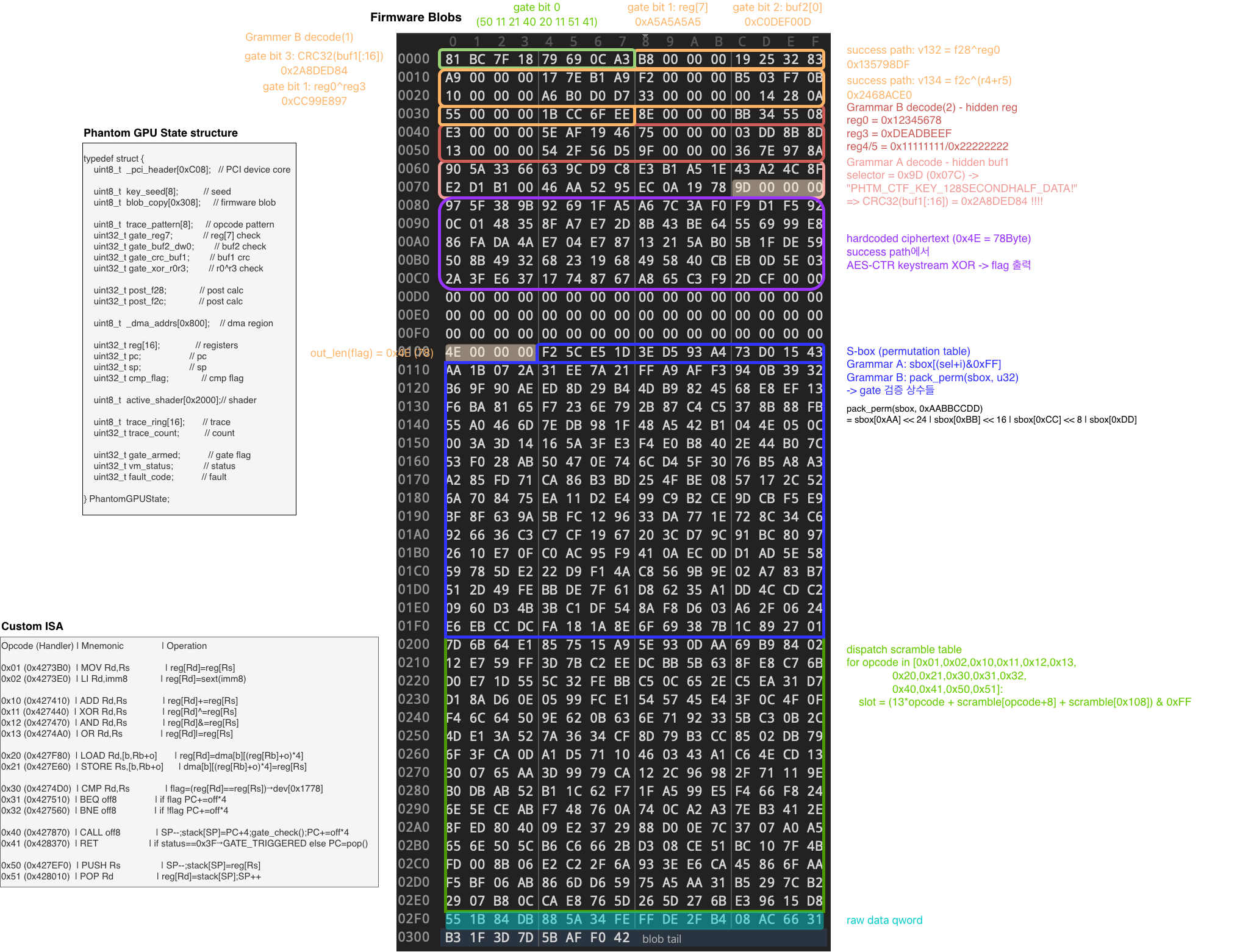
6. Gate Verification
6-1. Gate Condition Analysis
The RET handler (sub_428370) calls sub_4280D0 (checker) on every RET. If it returns exactly 0x3F (all 6 bits set), vm_status = 8 (GATE_TRIGGERED).
Bit 0 (0x01) — Trace History
Last 8 opcodes == 50 11 21 40 20 11 51 41(PUSH XOR STORE CALL LOAD XOR POP RET)Bit 1 (0x02) — Register Check
reg[7] == 0xA5A5A5A5reg[0] ^ reg[3] == 0xCC99E897Bit 2 (0x04) — buf2 First Dword
*(u32*)buf2 == 0xC0DEF00DBit 3 (0x08) — buf1 CRC32
CRC32(buf1[0:16]) == 0x2A8DED84The gate only checks the CRC of buf1’s first 16 bytes—not the actual byte values.
Bit 4 (0x10) — Gate Armed
On CALL execution: reg[1] == 0x47415445 ("ETAG") + previous 4 traces == [LOAD, AND, STORE, CALL]Bit 5 (0x20) — Shader CRC32
reg[2] == CRC32(entire shader bytecode)Dead code bytes are also included in the CRC calculation.
6-2. Gate Verification Bypass
Problem:
In the Bit 0 history 50 11 21 40 20 11 51 41, right before RET is a single 0x51 (POP), and before that is 0x11 (XOR). But the validator demands two POPs before any reachable RET. You can’t satisfy both constraints with reachable code alone.
Solution:
The validator doesn’t check CALL prologue/RET epilogue rules on dead code blocks. We can exploit that.
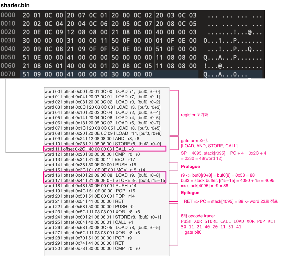
- Within a reachable function, use STORE to overwrite the return address in slot3 (stack) with the dead block PC
- End the function with POP + POP + RET that satisfies validator rules
- RET pops the overwritten address and jumps to the dead block
- In the dead block, create exactly the
50 11 21 40 20 11 51 41history - On the dead block’s final RET, checker is called →
0x3F→ GATE_TRIGGERED
Dead Block Return Address Overwrite
gpuctl-cli run allocates slot3 as 16KB (SP=4096). CALL pushes the return address to stack[4095], but STORE’s offset (byte3) is signed 8-bit—with base 0 you can only reach up to stack[15].
The trick: preload r14 = 4080 before CALL. The function prologue’s MOV r15, r14 gives us r15 = 4080, and STORE r9, [buf3, r15+15] lands exactly on stack[4095]. The validator checks the bytecode statically, so it can’t catch the same instructions writing to different locations depending on the runtime value of r14.
6-3. Shader Layout
The final shader has two regions: a reachable region and a dead block. The reachable region sets gate bits 1~5, then a return address overwrite jumps into the dead block to nail bit 0 (trace history) as well.
7. Flag Recovery
Even after hitting GATE_TRIGGERED, buf2 won’t contain the correct flag right away. The gate only checks relationships between registers and buffers (XOR, CRC, etc.), so tons of input combinations can pass. But the success path uses each value directly to derive the AES key—wrong inputs, wrong output.
7-1. Gate Check Scope
What the gate does fix:
- trace8 — 8-byte match
- reg7 — value match
- reg0 ⊕ reg3 — XOR result only (individual values are free)
- buf2[0:4] — value match
- CRC32(buf1[:16]) — CRC only (raw bytes are free)
- reg2 — CRC32(shader) match
What the gate does not check:
- Individual reg0, reg3 values
- reg4, reg5
- All 32 bytes of buf1 (first 16: CRC only, last 16: completely free)
7-2. What the Success Path Actually Reads
// sub_428AB0 success path, 0x4299d6..v132 = f28 ^ reg0 // uses reg0 directlyv134 = f2c ^ ((reg4 + reg5) & 0xFFFFFFFF) // uses reg4, reg5 directlyv135 = ROL32(reg3, 7) ^ v132 // uses reg3 directlymsg = trace8 || pack_le32(v135) || pack_le32(v134) || buf1[16:32]rounds = expand_round_material(buf1[0:16]) // uses raw buf1 bytes directlySo even after passing the gate, you still need to recover the exact individual values of reg0, reg3, reg4, reg5 and the precise 32 bytes of buf1 to get the real flag.
7-4. Success Path Analysis
buf1[0:32] ──┐trace8 ──┤reg0~reg5 ──┼──▶ compress_states() ──▶ S0 (AES key), S1 (CTR counter)f28, f2c ──┘ ↓ AES-128-CTR(S0, S1) ──▶ keystream (78B) │ fixed_blob (78B) ──XOR───────┘──▶ flag (buf2 output)Main logic of compress_states:
- Generate 24 round materials from
buf1[0:16](MurmurHash3 fmix variant) - GF(2^8) MixColumns (standard + custom matrix) + Feistel 12 rounds
fold16(sub_4279B0): 16B → 64-bit keyed digest (seed0xDEADBEEFCAFEBABE)- Reverse Feistel 8 rounds + final GF MixColumns → S0 (AES key), S1 (CTR counter)
This is a non-invertible one-way function, so reversing it seems impossible. However, since it runs automatically inside the VM with the correct inputs, further analysis isn’t necessary.
7-6. Hidden Witness
So the flag doesn’t pop out even after passing the gate—we need to find the exact input values the success path expects. Luckily, there’s still an uninterpreted region left in the firmware blob’s 0x308 bytes.
This part takes a bit of guessing:
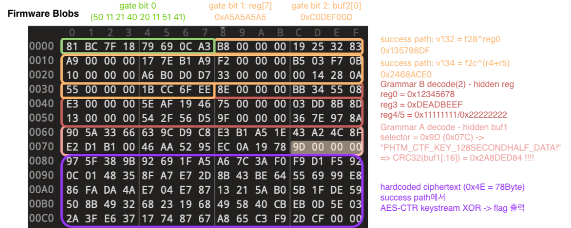
Hidden Registers
Decoding firmware blob 0x034..0x054 with Grammar B (pack_perm XOR):
| Value | Purpose |
|---|---|
0x12345678 | reg0 |
0xDEADBEEF | reg3 |
0x11111111 | reg4 |
0x22222222 | reg5 |
Verification: 0x12345678 ^ 0xDEADBEEF = 0xCC99E897 = exactly matches the expected reg0 ^ reg3 value for gate bit 1.
Hidden buf1
Firmware blob blob[0x5C:0x80] region:
[0x5C:0x7C] = raw 32 bytes (data encoded with Grammar A)[0x7C:0x80] = selector dword (0x0000009D)Same [raw data] + [selector dword] format as the Grammar A block used for trace8. Applying Grammar A:
decoded[i] = blob[0x5C + i] ^ sbox[(0x9D + i) & 0xFF]Out comes PHTM_CTF_KEY_128SECONDHALF_DATA!!
The identical [raw data] + [selector dword] format, a meaningful ASCII string, and CRC32 of the first 16 bytes = 0x2A8DED84 = exactly matching gate constant f20—all signs point to this being the intended buf1 value.
Note that hidden reg and buf1 aren’t referenced by the QEMU success path at runtime. These hidden markers are concealed values you need to discover, not answers the VM consumes directly.
8. Solve